Waste-to-Energy: ACI + SDA + FF + WESP Train Design for Optimal Emission Control and Efficiency
Waste-to-Energy (WTE) ACI + SDA + FF + WESP train design combines advanced air pollution control technologies for managing emissions in waste-to-energy plants. This system uses Activated Carbon Injection (ACI), Spray Dryer Absorber (SDA), Fabric Filter (FF), and Wet Electrostatic Precipitator (WESP) to capture pollutants like dioxins, mercury, acidic gases, and particulate matter.
These technologies help ensure municipal solid waste combustion produces energy with minimal environmental impact. Each component targets specific pollutants, working together for cleaner emissions and regulatory compliance.
ACI targets heavy metals and dioxins. SDA neutralizes acidic gases. FF traps particles. WESP removes ultrafine particles and residual contaminants.
This setup forms a comprehensive pollution control system, vital for WTE plants converting waste into renewable energy while protecting air quality. Industry studies on emission reduction and plant efficiency highlight this importance.
Overview of the ACI + SDA + FF + WESP Train in Waste-to-Energy

The ACI + SDA + FF + WESP train serves as a core air pollution control (APC) system in waste-to-energy (WtE) plants. This combination reduces emissions, captures fine particles, and controls acid gases for regulatory compliance.
Each device has a clear role. Their integration keeps plant operations efficient and compliant.
Purpose and Function of Each Component
Activated Carbon Injection (ACI) injects powdered activated carbon to adsorb pollutants like dioxins, furans, mercury, and acidic gases. This step reduces toxic emissions before filtration.
Spray Dryer Absorber (SDA) uses an alkaline slurry, usually lime or limestone, to neutralize acidic gases such as hydrogen chloride and sulfur dioxide. This prevents corrosion and helps meet acid gas limits.
Fabric Filter (FF) traps fly ash, activated carbon, and reaction products from the SDA. Fabric bags or cartridges filter particles down to 1 micron.
Wet Electrostatic Precipitator (WESP) acts as the final polishing unit. Electrical charge and water remove ultrafine particles and acid mists, ensuring the cleanest gas release.
Integration Within the Waste-to-Energy Process
The APC train starts with ACI, which targets toxic compounds formed during combustion. Treated gas then enters the SDA for acid gas neutralization.
FF captures most particles from combustion and chemical reactions. WESP follows, removing particulates too small for the FF.
This sequence maximizes contaminant removal by combining chemical and physical processes. The four units create a layered defense against emissions and integrate with the combustion system.
This setup links directly to steam-generation and power systems by keeping flue gas clean.
Importance for Modern Facility Design
Modern WtE facilities need to recover energy while meeting strict emissions standards. The ACI + SDA + FF + WESP train makes this possible with reliable, cost-effective pollution control.
This train handles variable waste compositions and helps facilities comply with regulations like the U.S. EPA’s Clean Air Act. By targeting particulates, heavy metals, acid gases, and toxic organics, WTE operations stay sustainable.
The system also protects equipment from corrosion and wear caused by acidic and fine particulate components. This extends plant life and reduces maintenance expenses, both critical for operational efficiency.
Facility-specific customization tailors the train design to waste type, flue gas makeup, and emission limits. That adaptability matters as waste-to-energy challenges evolve.
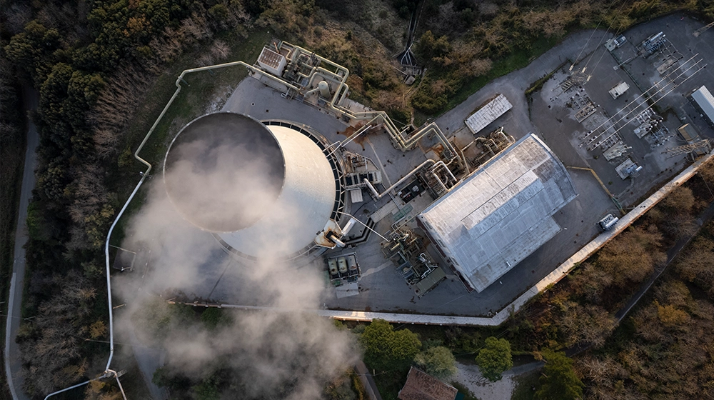
Incineration and Flue Gas Generation in Waste-to-Energy Plants
Waste-to-energy plants use incineration to turn waste into energy. Incineration generates flue gas, a mix of gases and particles that needs careful treatment.
Waste type, flue gas makeup, and combustion method all affect plant performance and emissions. These factors shape how well the process works and what comes out the stack.
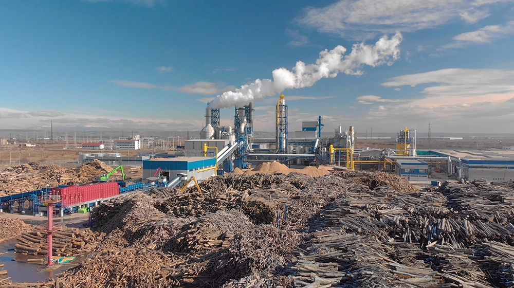
Types of Waste Suitable for Incineration
Municipal solid waste (MSW) forms the main feedstock—household trash, packaging, organics. Some industrial wastes, like non-recyclable plastics and sludge, also work if they follow environmental rules.
Hazardous or liquid wastes get excluded because they release harmful pollutants and complicate treatment. High-moisture waste burns less efficiently, so pre-drying or sorting often happens first.
Incineration works best with waste that has a reasonable calorific value. A 2019 Zero Waste Europe report, “CCS on Waste to Energy,” found that burning one ton of MSW releases 0.7 to 1.7 tons of CO₂, depending on waste type.
Flue Gas Composition and Challenges
Flue gas from waste-to-energy plants contains CO₂, water vapor, nitrogen, oxygen, and trace pollutants like dioxins, heavy metals, and acid gases (SO₂, HCl). Particulate matter and unburned compounds also appear and must be removed before release.
Key challenges include toxic emissions and corrosion from acidic gases. Flue gas volume shifts with waste composition, combustion temperature, and air supply.
Common flue gas purification methods include dioxin destruction, dust filtration (baghouse filters), dry or wet desulfurization, and reheating to prevent condensation of harmful substances. These methods form the backbone of modern flue gas cleaning trains like ACI, SDA, FF, and WESP.
Role of Combustion Technology
Combustion technology determines how efficiently waste burns and how much energy gets recovered. Modern incinerators use moving grates, fluidized beds, or gasification to boost combustion and reduce ash.
Combustion temperature, airflow, and mixing affect pollutant formation and how completely waste burns. Higher temperatures break down harmful organics like dioxins, and stable conditions help curb nitrogen oxide (NOₓ) formation.
Advanced plants recover heat in steam boilers. Steam drives turbines for electricity and heating, feeding into power grids or district heating. Efficient combustion cuts emissions and maximizes output, which is crucial for both environmental and economic goals.
Activated Carbon Injection (ACI) for Pollutant Control
Activated Carbon Injection (ACI) controls mercury, dioxins, and other organic pollutants in waste-to-energy plants by injecting powdered activated carbon (PAC) into flue gas. System design, operational setup, and handling procedures impact effectiveness.
Proper ACI design integrates with downstream equipment like fabric filters (FF) and wet electrostatic precipitators (WESP) to maximize pollutant capture and maintain compliance.
Mechanism of Pollutant Adsorption
ACI works by injecting fine powdered activated carbon into the flue gas stream. Porous carbon particles adsorb mercury vapor and organic compounds as gas moves through.
This step reduces toxic pollutants before gas hits emission controls like fabric filters. Activated carbon’s large surface area enables high adsorption capacity.
Mercury binds tightly to the carbon, limiting atmospheric release. Adsorption depends on carbon properties, flue gas temperature, and pollutant concentration. Different activated carbons suit different pollutants and fuel mixes.
This adsorption complements downstream removal, with many setups achieving over 90% mercury removal. A 2020 U.S. Environmental Protection Agency report on mercury control technologies supports this.
Design Considerations for Efficient ACI
Good ACI design balances injection rate, placement, and carbon particle size for optimal removal. The system must deliver a steady carbon dose matched to flue gas volume and content.
Key factors:
- Injection location works best before particulate control for maximum contact.
- Reliable feeders prevent blockages and keep flow steady.
- Integration with fabric filters, SDA, and WESP keeps captured pollutants contained.
Cooler gas streams improve mercury adsorption. High injection rates boost effectiveness but raise costs and filter loading, so trade-offs matter. A 2022 BulkInside study, “Activated Carbon Injection (ACI) Systems,” highlights these factors for efficient, cost-effective design.
Handling and Maintenance
Proper storage of powdered activated carbon prevents downtime and contamination. PAC stays dry in sealed bulk bags or bins with activators to avoid clumping and moisture.
Routine maintenance includes checking feeders, valves, and injection nozzles to prevent clogs. Cleaning keeps carbon flow smooth and injection rates steady.
Monitoring pressure and feed rates catches blockages early. Maintenance routines differ by plant size and system complexity but all aim to cut labor and operational costs while keeping reliability high.
A 2019 Metalfab technical brief pointed out that integrated storage and feeding designs reduce maintenance issues and boost uptime in coal and waste-to-energy facilities.
Spray Dry Absorber (SDA) System Design
The Spray Dry Absorber (SDA) system controls acidic gases in waste-to-energy plants. An alkaline slurry gets atomized into hot flue gas, reacting with acid gases like SO₂ and HCl to form solid salts.
Design focuses on chemical neutralization, process control, and integration with other pollution controls. Understanding these design principles helps optimize pollutant removal and keep operations efficient in a complex emission control train.
Neutralization of Acidic Gases
The SDA system neutralizes acid gases by spraying a fine alkaline slurry—usually slaked lime (calcium hydroxide)—into the hot flue gas.
This slurry’s alkalinity reacts with sulfur dioxide (SO2), hydrochloric acid (HCl), and other acidic components.
The reaction forms dry, stable salts collected downstream.
Absorber temperature stays between 160°C and 200°C for good reaction rates.
Critical features of neutralization include:
- Slurry concentration and droplet size: Smaller droplets mean more surface area for reactions.
- Gas residence time: Longer contact helps complete neutralization.
- Reagent stoichiometry: Lime dosage needs to match acid gas levels.
The International Energy Agency’s 2023 report, “Gas Emission Control Technologies,” states that well-designed SDA systems remove 85-95% of SO2, depending on setup and conditions.
Critical Parameters for SDA Operation
Several parameters shape SDA performance and reliability.
- Slurry Feed Rate: Consistent flow and concentration help avoid plugging or incomplete reactions.
- Atomization Pressure: Fine droplets require pressure, usually between 4 and 7 bar.
- Flue Gas Temperature: Keeping gas between 160°C and 200°C prevents moisture issues and sustains reactions.
- pH Control: Slurry pH influences reactivity and byproducts.
- Spray Pattern and Coverage: Even distribution in the absorber ensures thorough contact.
- Pressure Drop: Low pressure drop cuts down on fan energy use.
The 2024 Journal of Environmental Engineering review, “Optimization of Spray Dryer Absorbers in Waste-to-Energy Plants,” highlights the need to balance these factors for top removal rates and lower maintenance.
Integration With Downstream Technologies
SDA systems work best alongside fabric filters (FF) and wet electrostatic precipitators (WESP).
After neutralization, fabric filters collect dry salts, dust, and particulates. Filters must withstand the SDA product’s moisture and alkalinity.
Some setups add a WESP after the FF to catch even finer particles and acid mist, tightening emission control.
Integration focuses on:
- Matching gas flows and temperatures between units.
- Coordinating maintenance to prevent downtime.
- Handling byproducts for safe disposal or reuse.
Siemens Environmental Systems’ 2022 white paper notes that linking SDA, FF, and WESP often achieves more than 99% removal of acidic gases and particulates in waste-to-energy plants.
Fabric Filter (FF) and Fine Particle Removal
Fabric filters (FF) capture fine particles from waste-to-energy flue gas by forcing gas through tightly woven fabric.
Filter material, cleaning approach, and ash handling affect efficiency and operational cost, shaping particulate control and system reliability.
Selection of Filter Materials
Fabric filters use materials like polyester, fiberglass, or PTFE-coated fabrics.
Choice depends on flue gas temperature, chemicals, and particle traits. Fiberglass tolerates high heat but can degrade with acidic gases. Polyester costs less and works for moderate conditions but handles less heat.
Fabric selection balances durability with filtration. Tighter weaves trap more particles but raise pressure drop. Surface treatments reduce particle sticking, easing cleaning cycles.
Compatibility with spray dryer absorbers (SDA) or wet electrostatic precipitators (WESP) also matters. A good match avoids corrosion or damage from flue gas chemistry.
Performance Optimization
Performance relies on airflow velocity, cleaning schedule, and filter cake removal.
Keeping gas velocity in check prevents filter damage and ensures steady capture. Pulse-jet or air-wash cleaning restores permeability by removing dust.
Efficiency shifts as filter cake builds and cleaning cycles run. Consistent cleaning avoids overusing compressed air and cuts fabric wear. Monitoring pressure drop and gas characteristics guides adjustments.
Pairing fabric filters with activated carbon injection (ACI) and SDA improves removal of fine particulates and hazardous pollutants while managing costs.
Ash Handling and Disposal
Fabric filters collect dry ash, making handling simpler than wet scrubber waste.
Good ash removal systems prevent clogs and keep airflow steady. Rotary valves or screw conveyors move ash away efficiently.
Ash disposal depends on its makeup. Heavy metals or unburned carbon may require special treatment. Recycling or landfilling follows regulations.
Effective ash management reduces downtime and hazards, supporting smooth downstream operation in the waste-to-energy process.
Wet Electrostatic Precipitator (WESP) Integration
The Wet Electrostatic Precipitator (WESP) removes fine particles and pollutants from flue gases in waste-to-energy plants.
Integration involves specific operating principles, ultrafine particulate control, and careful water management to keep efficiency high and protect downstream equipment.
Principles of WESP Operation
WESP units use electric fields to charge particles in wet flue gas streams.
Charged particles stick to grounded plates, which water washes continuously to remove buildup.
Unlike dry ESPs, WESP designs keep collection surfaces wet, stopping particle re-entrainment.
This approach captures aerosols, acid mists, and submicron particles very well.
High-voltage power supplies, discharge electrodes, collection plates, and water flushing systems make up the core components.
Operators control voltage, current, and water flow to optimize performance.
Maintaining the right electrical and temperature conditions drives WESP effectiveness. Monitoring secondary voltage and inlet/outlet temperatures helps keep collection rates high.
Control of Ultrafine Particulates and Aerosols
WESPs excel at catching ultrafine particles under 1 micron—particles traditional filters struggle with.
The strong electric field charges these tiny particles for collection, even in wet conditions.
WESPs also trap acid mists and condensed organic aerosols, including sulfuric acid mist common in waste-to-energy gas streams.
The wet design prevents buildup and clogs found in dry filters. Continuous washing keeps pressure drop low and filtration steady.
Adding WESP to waste-to-energy setups improves control over toxic metals and fine particulates, helping meet tough air quality standards.
Water Management Strategies
Water quality and flow are critical for WESP function.
Flushing water must stay clean to avoid scaling and corrosion on plates and electrodes.
Water treatment systems filter out large and fine solids, keeping water in good shape. Drum screens and flotation units help remove debris that could hurt performance.
Controlling water temperature matters too. Cold water can lower collection efficiency, so operators monitor and adjust inlet temperatures as needed.
Smart water management keeps consumption and wastewater down, supporting plant sustainability. Clean water protects downstream equipment from blockages or corrosive deposits.
Environmental Impact and Compliance Considerations
Waste-to-Energy (WtE) systems—like the ACI + SDA + FF + WESP train—operate under strict environmental standards to control emissions and stay compliant with changing regulations.
Design brings environmental benefits, but ongoing monitoring and reporting are essential for compliance and risk reduction.
Emission Standards and Regulatory Requirements
These systems must meet national and international emission limits for pollutants like dioxins, furans, particulate matter, NOx, SO2, and heavy metals.
Regulations often follow air quality standards from agencies such as the EPA or European Commission.
Key requirements include continuous emission monitoring, strict permitting, and regular environmental impact assessments.
The treatment train cuts harmful emissions through acid gas removal (ACI), scrubber absorption (SDA), fabric filtration (FF), and wire electrostatic precipitation (WESP), each targeting specific pollutants.
Health and safety rules require careful handling of residuals and fly ash to avoid secondary contamination. Adhering to these rules protects the environment and public health while supporting sustainable energy recovery.
Advantages of the Combined Train Design
The integrated ACI + SDA + FF + WESP setup boosts pollutant removal and environmental control over single-stage systems.
- ACI (Activated Carbon Injection): Adsorbs mercury and dioxins.
- SDA (Spray Dry Absorber): Neutralizes acidic gases such as SO2.
- FF (Fabric Filter): Captures fine dust and particulates.
- WESP (Wet Electrostatic Precipitator): Removes submicron particles, raising total emission reduction.
This combination cuts toxic emissions, improves air quality, and reduces greenhouse gases.
The design adapts to different waste types and operating conditions, supporting compliance with evolving regulatory standards.
Monitoring and Reporting Best Practices
Continuous emission monitoring systems (CEMS) track pollutants in real time.
Data on gases, dust, and heavy metals gets logged and reported to regulators.
Best practices include sensor calibration, routine maintenance, and data validation to avoid errors. Transparent reporting helps operators spot issues early and act fast.
Emission reports should cover:
- Pollutant concentrations
- Operational parameters (temperature, flow rates)
- Compliance status with regulatory limits
These steps build regulatory trust and encourage transparency. Training staff in data management and compliance helps meet goals and protect public health.
The International Environmental Agency’s 2023 review, “Environmental Regulations and Challenges in Waste-to-Energy Projects,” says ongoing monitoring strengthens compliance and drives improvement in waste-to-energy operations.
Frequently Asked Questions
Waste-to-Energy plants using ACI (Activated Carbon Injection), SDA (Spray Dry Absorber), FF (Fabric Filter), and WESP (Wet Electrostatic Precipitator) rely on complex systems to control emissions and recover energy.
These components work together to manage acid gases, remove particulates, and ensure cleaner exhaust, supporting efficient energy production.
The questions below address the plant’s main systems, acid gas control, energy efficiency, emissions, equipment operation in tough conditions, and maintenance challenges.
What are the main components of a Waste-to-Energy plant using ACI, SDA, FF, and WESP technologies?
Key systems in a modern Waste-to-Energy plant include several specialized units.
- Activated Carbon Injection (ACI) injects activated carbon directly into the flue gas stream. This process captures mercury and dioxins right at the source.
- Spray Dry Absorber (SDA) uses a lime slurry spray. The lime reacts with acid gases like SO2 and HCl, neutralizing them on contact.
- Fabric Filter (FF) acts as a massive dust collector. Fine particulate matter gets trapped in these filter bags.
- Wet Electrostatic Precipitator (WESP) steps in to grab whatever FF lets through. WESP pulls out ultrafine particles and mist, offering a final layer of cleanup.
How does the Acid Gas Control integrate with the overall Waste-to-Energy process?
Acid gas control sits right at the heart of emissions management in Waste-to-Energy plants. Combustion releases a surge of acid gases, so the SDA gets positioned after the boiler to neutralize these compounds quickly.
Activated Carbon Injection targets toxic trace gases upstream. Fabric Filters and WESP follow, handling solid and ultrafine particles. This layered approach builds a robust defense against air pollutants in the flue gas.
What are the efficiency rates for energy production in a plant incorporating ACI, SDA, FF, and WESP systems?
Energy conversion rates in these facilities typically land between 20% and 28%. That means about a quarter of the waste’s heat content becomes electricity.
Air pollution control equipment like ACI, SDA, FF, and WESP draws some power. Still, these systems focus on cleaning emissions, not energy recovery, so their impact on overall efficiency stays limited.
What are the typical emissions levels from a Waste-to-Energy facility using these technologies?
Plants running ACI, SDA, FF, and WESP can push emissions down to impressively low levels. Typical figures include:
- Particulate matter usually falls below 10 mg/m³,
- SO2 and HCl drop to nearly undetectable levels,
- Mercury and dioxins get captured thanks to ACI,
- Heavy metals and ultrafine particles remain under control with FF and WESP.
Can the FF and WESP systems operate effectively in high particulate environments commonly found in Waste-to-Energy plants?
Fabric Filters handle heavy dust loads with ease. Filter bag cleaning cycles keep performance steady, even in tough conditions.
WESP tackles the leftover ultrafine particles and aerosols. The wet environment inside WESP stops particles from escaping back into the gas stream, so efficiency stays high even when things get dusty.
What are the maintenance and operational challenges associated with a Waste-to-Energy train design that includes ACI, SDA, FF, and WESP?
Maintenance teams regularly replace filter bags in the fabric filter (FF). Electrode plates in the wet electrostatic precipitator (WESP) need cleaning to stop build-up, which can get out of hand fast if neglected.
The spray dryer absorber (SDA) relies on a lime slurry system that demands constant monitoring. Scaling and blockages can pop up if operators aren’t careful.
Activated carbon injection (ACI) setups depend on a steady flow and precise control of activated carbon. Balancing how much reagent gets used with strict emissions limits isn’t always straightforward.
Keeping everything running smoothly during shifts in waste feed and combustion conditions adds another layer of complexity. Reliability sometimes feels like a moving target in this business.